Q1) Define Operating System?
From the user point of view:
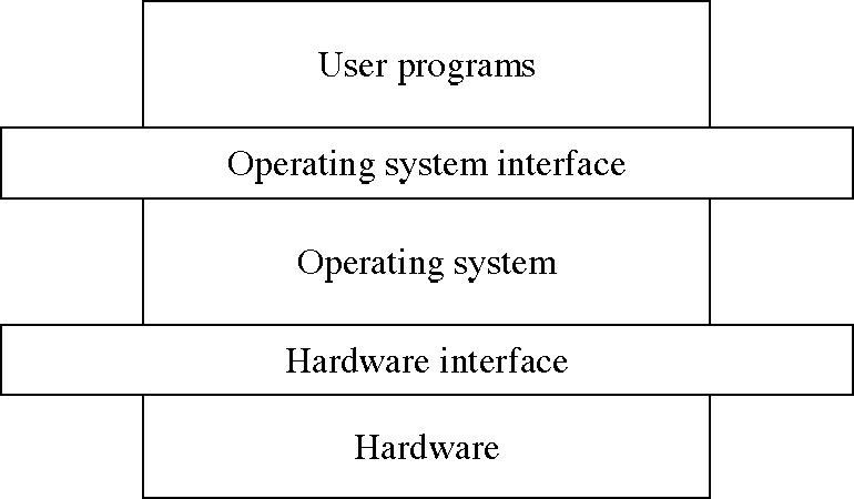
O.S should be easy to use an application. Hence Operating system is an interface between user and computer hardware.
when it comes to the view point of a system:
O.S needs to ensure that system resources are utilized efficiently. Hence Operating system is resource manager.
Levels in computer system are as shown in diagram below
Q2) Explain Processor Modes?
https://www.youtube.com/watch?v=jbanf11B3Ug
There are 2 operating modes in the CPU; the kernel mode and the user mode. To ensure proper execution of operating system there must be a way to distinguish between user code and operating system code. For this purpose, one bit is maintained in Hardware. That bit is called mode bit. When the mode bit is zero then the system is said to be in kernel mode and when this mode bit is 1 then the system is said to be in user mode.
Whenever the computer execute some code on behalf of user application then it is said to be in user mode and at that time this mode bit will be 1.
When the operative system gains control over the computer system then it is said to be in kernel mode and at that time this mode bit should be 0.
Kernel mode is also called supervisor mode or system mode. It is also called privileged mode.
Whenever the computer system is executing on behalf of a user application then the system is in user mode. But when this user application requests service from operating system through system call then at that time there must be a transition from user mode to kernel mode
To protect the operating system from end users, the machine instructions which can cause harm are designated as privileged instructions. Hardware allows these privileged instructions to be executed only in kernel mode.
Q3) How to make a System call?
System call is a special machine instruction that causes an interrupt. Example: syscall, trap, svc. There are some tasks which can be performed only by the operating system. So user program asks the operating system to perform these tasks on its behalf by system call. So system call provides a way to a user program by which it can ask the operating system to perform these tasks. Whenever a system call is executed,
it is treated by the hardware as a software interrupt (software interrupt is nothing but system call)
and through interrupt vector, control passes to interrupt handler service routine in the operating system
and the mode bit is set to the kernel mode
then kernel examines the interrupting instruction and determines the type of system call and checks whether the user has the privilege, then kernel executes the request and
it returns the control to the instruction following the system call in the user program.
Example:
#include <stdio.h>
int main()
{
printf("hello, world!\n");
return 0;
}
The above program uses printf, which makes a system call to write those bytes to stdout. stdout is standard output, which is by default monitor.
https://www.youtube.com/watch?v=ru-ouiqVDqc
Q4) What are the IPC related system calls?
Answer:
Processes execute to accomplish specified computations Often it is possible to partition a computational task into segments which can be distributed amongst several processes. Clearly, these processes would then form a set of communicating processes which cooperate in advancing a solution.
Different IPC mechanisms are pipes, shared memory and message queues.
Pipes, as used in commands like ls|more, direct the output stream of one process to feed the input of another process. So for IPC, we need to create a pipe and identify the direction of feeding the pipe. Another way to communicate would be to use memory locations. We can have one process write into a memory location and expect the other process to read from it. In this case the memory location is a shared memory location. Finally, there is one more mechanism in which one may send a message to another process. The receiving process may interpret the message. Usually, the messages are used to communicate an event.
System calls used in IPC mechanism, pipes:
pipe() system call would create a pipe for one-way communication i.e., it creates two descriptors, first one is connected to read from the pipe and other one is connected to write into the pipe.
read() and write() system calls are used to read and write to a specified file.
System calls used in IPC mechanism, shared memory
shmget() system call creates or allocates a System V shared memory segment.
shmat() system call attaches a shared memory segment to the address space of the calling process.
shmctl() system call performs control operation for a System V shared memory segment.
System calls used in IPC mechanism, message queues in system V UNIX are:
ftok(): is use to generate a unique key.
msgget(): either returns the message queue identifier for a newly created message queue or returns the identifiers for a queue which exists with the same key value.
msgsnd(): Data is placed on to a message queue by calling msgsnd().
msgrcv(): messages are retrieved from a queue.
msgctl(): It performs various operations on a queue. Generally it is used to destroy message queue.
Q5) Discuss about communicating with Pipes?.
Answer: Pipe is a mechanism for inter process communication. It uses the familiar file interface. Communication is achieved by one process writing into the pipe and other reading from the pipe
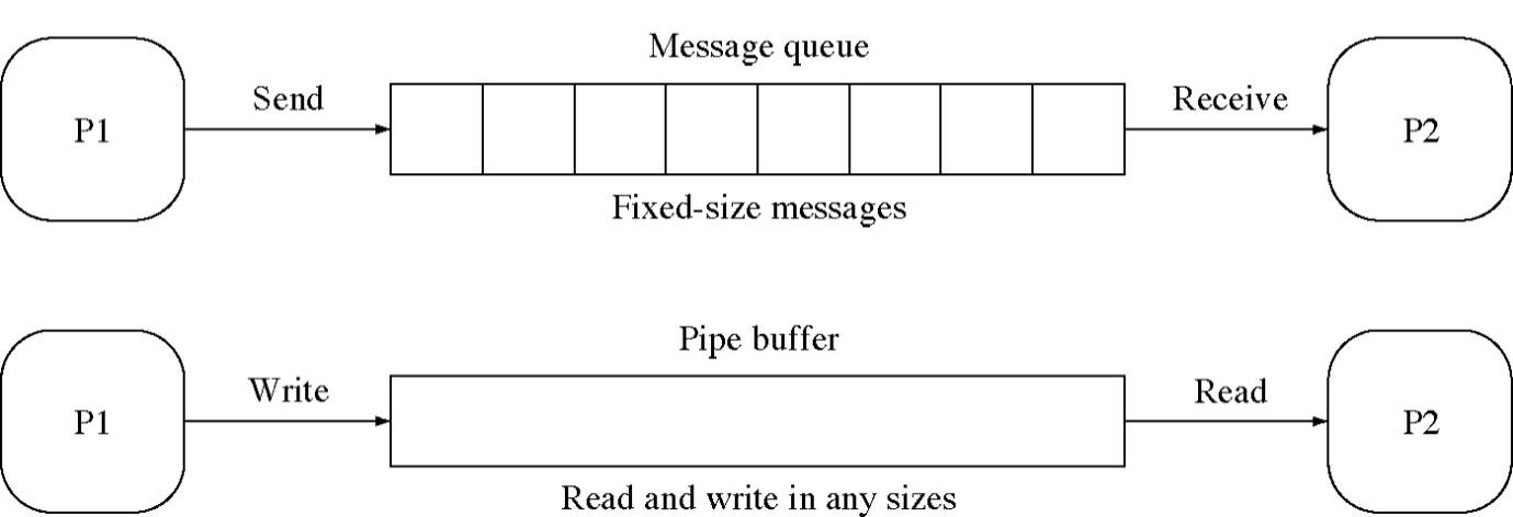
In the above diagram, pipe connects the standard output (write) of one process to the standard input(read) of another process as shown.
System call to create pipe:
#include<unistd.h>
int pipe(int fd[2]);
This system call would create a pipe for one-way communication i.e., it creates two descriptors, fd[0] and fd[1]. Descriptor fd[0] is for reading and fd[1] is for writing. Whatever is written into fd[1] can be read from fd[0].
This pipe() system call would return zero on success and -1 in case of failure. To know the cause of failure, check with errno variable or perror() function.
#include<unistd.h>
ssize_t read(int fd, void *buf, size_t count)
The above system call is to read from the specified file with arguments of file descriptor fd, proper buffer with allocated memory (either static or dynamic) and the size of buffer.
The file descriptor id, fd is to identify the respective file, which is returned after calling open() or pipe() system call. The file needs to be opened before reading from the file. It automatically opens in case of calling pipe() system call.
This call would return the number of bytes read (or zero in case of encountering the end of the file) on success and -1 in case of failure.
#include<unistd.h>
ssize_t write(int fd, void *buf, size_t count)
The above system call is used to write to the specified file.
https://www.youtube.com/watch?v=wQUY2W49xjQ
https://www.youtube.com/watch?v=QRKn32A3eeY
Q6) Define Process creation.
Answer:
(i). When a new process is created, operating system assigns a unique Process Identifier (PID) to it and inserts a new entry in primary process table.
(ii). Then the required memory space for all the elements of process such as program, data and stack is allocated including space for its Process Control Block (PCB).
(iii). Next, the various values in PCB are initialized such as,
Process identification part is filled with PID assigned to it and its parent’s PID.
The processor register values are mostly filled with zeroes, except for the stack pointer and program counter. Stack pointer is filled with the address of stack allocated to it and program counter is filled with the address of its program entry point.
The process state information would be set to ‘New’.
Priority would be lowest by default, but user can specify any priority during creation.
In the beginning, process is not allocated any I/O devices or files. The user has to request them or if this is a child process it may inherit some resources from its parent.
(vi). Then the operating system will link this process to scheduling queue and the process state would be changed from ‘New’ to ‘Ready’. Now process is competing for the CPU.
(v). Additionally, operating system will create some other data structures such as log files or accounting files to keep track of processes activity.
Q7. What is Linking and Loading a process?
Answer:
Loading: Bringing the program from secondary memory to main memory is called Loading.
Linking: Establishing the linking between all the modules or all the functions of the program in order to continue the program execution is called linking.
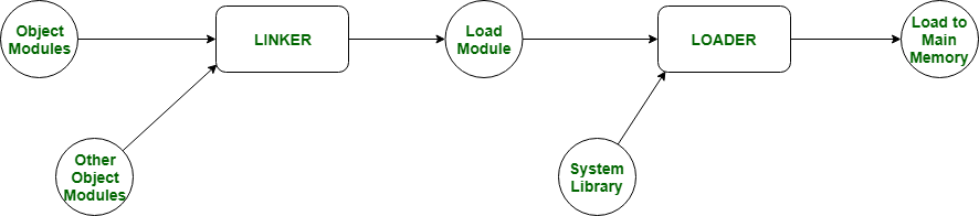
Loading and Linking are further categorized into 2 types:
https://www.youtube.com/watch?v=i6gPBm-zOXc
Q8) What is Fragmentation?
Answer: Fragmentation is an unwanted problem where the memory blocks cannot be allocated to the processes due to their small size and the blocks remain unused. It can also be understood as when the processes are loaded and removed from the memory they create free space or hole in the memory and these small blocks cannot be allocated to new upcoming processes and results in inefficient use of memory. Basically, there are two types of fragmentation:
Internal Fragmentation
External Fragmentation
Internal Fragmentation: In this fragmentation, the process is allocated a memory block of size more than the size of that process. Due to this some part of the memory is left unused and this cause internal fragmentation.
External Fragmentation: In this fragmentation, although we have total space available that is needed by a process still we are not able to put that process in the memory because that space is not contiguous. This is called external fragmentation.
https://afteracademy.com/blog/what-is-fragmentation-and-what-are-its-types
Q9) Define Page Replacement?
Answer:
Page Replacement Algorithm decides which page to remove, also called swap out when a new page needs to be loaded into the main memory. Page Replacement happens when a requested page is not present in the main memory and the available space is not sufficient for allocation to the requested page.
When the page that was selected for replacement was paged out, and referenced again, it has to read in from disk, and this requires for I/O completion. This process determines the quality of the page replacement algorithm: the lesser the time waiting for page-ins, the better is the algorithm.
A page replacement algorithm tries to select which pages should be replaced so as to minimize the total number of page misses. There are many different page replacement algorithms. These algorithms are evaluated by running them on a particular string of memory reference and computing the number of page faults. The fewer is the page faults the better is the algorithm for that situation.
If a process requests for page and that page is found in the main memory then it is called page hit, otherwise page miss or page fault.
Some Page Replacement Algorithms :
First In First Out (FIFO)
Least Recently Used (LRU)
Optimal Page Replacement
https://afteracademy.com/blog/what-are-the-page-replacement-algorithms
Q10) What is a Working Set?
Answer:
If a process is allocated too few frames, then there will be too many and too frequent page faults. As a result, no useful work would be done by the CPU and the CPU will be spending more time bringing the faulted page from secondary memory to main memory. As the CPU utilization would be low, the long-term scheduler would then try to improve the CPU utilisation by loading some more processes into the memory thereby increasing the degree of multiprogramming. A process is thrashing if it is spending more time paging than executing.
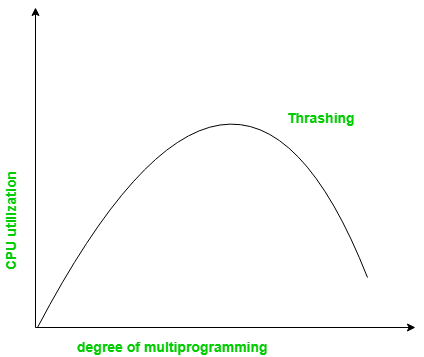
One of the Solution to Thrashing is Working Set strategy
Working Set Model model is based on the concept of the Locality Model. Here Locality is set of pages that are actively used together. Locality model states that as the process executes it moves from locality to locality. If we allocate enough frames to a process to accommodate the size of current locality, it will not fault again until it changes current locality.
Working Set model uses working-set and a parameter ∆ = working-set window
The set of pages in the most recent ∆ page references is the working set
Let WSSi be the working-set size for process Pi i.e, Pi needs WSSi frames
Let D be the total demand for frames then D=WSSi
If m be the total number of available frames and
If D>m , thrashing occurs because some processes will not have enough frames. So, the operating system
selects a process to suspend. The suspended process's pages are written out (swapped), and its frames are reallocated to other processes.
else if D < m then operating system may initiate another process.
The working set strategy prevents thrashing while keeping the degree of multi programming as high as possible.
The main difficulty is to keep track of moving working set window.
Q) Explain about different CPU or processor scheduling algorithms.
Answer:
https://www2.latech.edu/~box/os/ch05.pdf
The objective of multiprogramming is always to have some process running, to maximize CPU utilization.
There will be many processes in the ready queue ready to execute at a given time. Short-term scheduler selects from among the processes in Ready Queue that are ready to execute, and allocates the CPU to one of them.
CPU Scheduling algorithm can be categorized in two ways
1. Preemptive Scheduling: allows a process to be interrupted in the middle of its CPU execution, taking the CPU away to another process.
2. Non-Preemptive Scheduling : CPU cannot be taken away from the running process in the middle by another process. CPU is released only when the running process releases CPU.
Scheduling Criteria to decide CPU scheduling algorithm
1. CPU utilization – keep the CPU as busy as possible
2. Throughput – number of processes that complete their execution per time unit
3. Turnaround time – amount of time to execute a process
Turnaround time = (finishing time – arrival time)
or
Turnaround time = (waiting time + burst time)
4. Waiting time – amount of time a process has been waiting in the ready queue
5. Response time – amount of time it takes from when a request was submitted until the first response is produced.
An efficient algorithm must have maximum cpu utilization and throughput. It must have minimum turnaround, waiting and response time.
Different CPU Scheduling Algorithms are
1) First-Come, First-Served (FCFS) Scheduling: First come first served CPU scheduling algorithm is
non pre-emptive
Processes are scheduled in the order they have arrived.
FCFS is implemented by Queue. When the CPU is free, it is allocated to the process at the head of the queue.
Advantages: Easy to implement
Disadvantages: 1. Average waiting time is quite long
2. Convoy effect (it occurs as small processes wait in queue for big process to leave CPU)
Example:
Suppose that the processes arrive in the order: P1 , P2 , P3
The Gantt Chart for the schedule is:
0 24 27 30
Waiting time for P1 = 0; P2 = 24; P3 = 27
Average waiting time: (0 + 24 + 27)/3 = 17
2). Shortest-Job-First (SJF) Scheduling
Schedule the Process with shortest burst time.
If CPU burst time of two processe are same then FCFS is used
Advantages: Average waiting time decreases
Disadvantages: It is difficult to know the length of next CPU burst.
SJF can be either pre-emptive (or) non pre-emptive
1. Non pre-emptive SJF – once CPU is given to the process it cannot be preempted until completes its CPU burst.
2. Pre-emptive SJF (or) Shortest-Remaining-Time-First (SRTF). If the newly arrived process is shorter than what is remaining of currently executing process
then pre-empt the currently executing process.
Example: Process Arrival Time Burst Time
P1 0.0 7
P2 2.0 4
P3 4.0 1
P4 5.0 4
SJF (non-preemptive) Gantt Chart
0 7 8 12 16
Average waiting time = [0 +(8-2)+(7-4) +(12-5)] /4 =4
Example of Preemptive SJF
Process Arrival Time Burst Time
P1 0.0 7
P2 2.0 4
P3 4.0 1
P4 5.0 4
SJF (preemptive)
0 2 4 5 7 11 16
Average waiting time = (9 + 1 + 0 +2)/4 =3
3). Priority Scheduling
A priority number (integer) is associated with each process
The CPU is allocated to the process with the highest priority (smallest integer ≡ highest priority).
If two processes have equal priority then FCFS is used
SJF is a priority algorithm in which larger the CPU burst, lower the priority.
There are two schemes.
1. Preemptive
2. nonpreemptive
Problem ≡ Starvation – low priority processes may never execute.
Solution ≡ Aging – as time progresses increase the priority of the process.
Example:
Gantt chart:
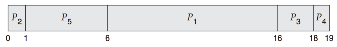
Average waiting time = (6 + 0 + 16 + 18 + 1) / 5 = 8.2 ms.
4). Round Robin (RR)
Each process gets a small unit of CPU time (time quantum), usually 10-100 milliseconds. After this time has elapsed, the process is preempted and added to the end of the ready queue.
If there are n processes in the ready queue and the time quantum is q, then each process gets 1/n of the
CPU time in chunks of at most q time units at once. No process waits more than (n-1)q time units.
Performance
1. q large _ FIFO
2. q small _ q must be large with respect to context switch, otherwise overhead is too high.
Example of RR with Time Quantum = 4
Process Burst Time
P1 24
P2 3
P3 3
The Gantt chart is:
0 4 7 10 14 18 22 26 30
Average waiting time = [(30-24)+4+7]/3 = 17/3 =5.66
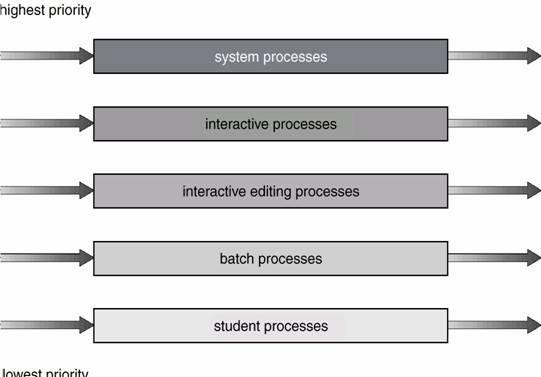
5)Multilevel Queue scheduling
Ready queue is partitioned into separate queues:
For ex: ready queue is divided into 2 queues
foreground (interactive) queue
background (batch) queue
Each queue has its own scheduling algorithm,
For ex: Round Robin scheduling algorithm can be used in foreground queue
FCFS scheduling algorithm can be used in background queue
Scheduling must be done between the queues. This can be done in 2 ways
Fixed priority scheduling
Foreground queue has highest priority. All the processes in foreground queue must be completed and queue must be empty. Then only the processes in background queue will be given CPU. As shown in below figure.
Disadvantage: starvation.
2. Time slice – each queue gets a certain amount of CPU time
which it can schedule amongst its processes; i.e., 80% to foreground in RR and 20% to background in FCFS
6) Multilevel Feedback Queue Scheduling
A process can move between queues. The idea is to separate processes according to their CPU bursts.
I/O – bound and interactive processes will be in highest priority queue.
If a process takes more CPU time, it is moved to lower priority queue.
If a process waits too long in lower priority queue, it is moved to higher priority queue to prevent starvation.
As shown in the below figure, let there be 3 queues Q0, Q1, Q2.
1. Q0 – time quantum 8 milliseconds
2. Q1 – time quantum 16 milliseconds
3. Q2 – FCFS
Scheduling
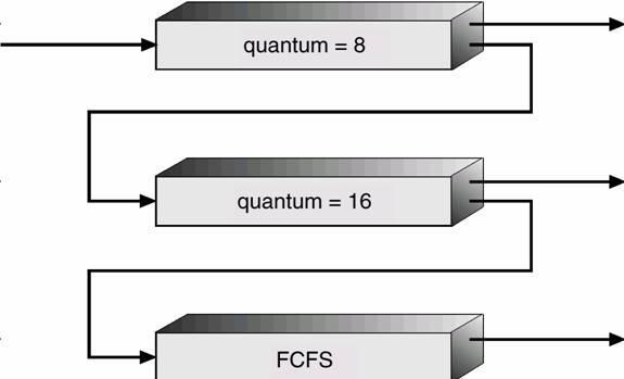
1. A process entering ready queue is put in queue Q0 When it gains CPU, the process receives 8 msec.
If it does not finish in 8 milliseconds, process is moved to queue Q1.
2. At Q1, process again receives 16 additional milliseconds. If it still does not complete, it is moved to queue Q2.
Q) Discuss First In First Out Page Replacement Algorithm with Example
This is the simplest page replacement algorithm. In this algorithm, the OS maintains a queue that keeps track of all the pages in memory, with the oldest page at the front and the most recent page at the back.
When there is a need for page replacement, the FIFO algorithm, swaps out the page at the front of the queue, that is the page which has been in the memory for the longest time.
For Example:
Consider the page reference string of size 12: 1, 2, 3, 4, 5, 1, 3, 1, 6, 3, 2, 3 with frame size 4(i.e. maximum 4 pages in a frame).
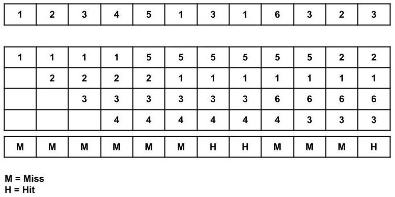
Total Page Fault = 9
Initially, all 4 slots are empty, so when 1, 2, 3, 4 came they are allocated to the empty slots in order of their arrival. This is page fault as 1, 2, 3, 4 are not available in memory.
When 5 comes, it is not available in memory so page fault occurs and it replaces the oldest page in memory, i.e., 1.
When 1 comes, it is not available in memory so page fault occurs and it replaces the oldest page in memory, i.e., 2.
When 3,1 comes, it is available in the memory, i.e., Page Hit, so no replacement occurs.
When 6 comes, it is not available in memory so page fault occurs and it replaces the oldest page in memory, i.e., 3.
When 3 comes, it is not available in memory so page fault occurs and it replaces the oldest page in memory, i.e., 4.
When 2 comes, it is not available in memory so page fault occurs and it replaces the oldest page in memory, i.e., 5.
When 3 comes, it is available in the memory, i.e., Page Hit, so no replacement occurs.
Page Fault ratio = 9/12 i.e. total miss/total possible cases
Advantages
Simple and easy to implement.
Low overhead.
Disadvantages
Poor performance.
Doesn’t consider the frequency of use or last used time, simply replaces the oldest page.
Suffers from Belady’s Anomaly(i.e. more page faults when we increase the number of page frames).
Q) Explain Approximations of LRU?
1) Using reference bit
2) Using additional reference bits algorithm
3) Second chance algorithm
4) Enhanced Second chance algorithm
5) Counting based Page replacement
Has two schemes
1) Least Frequently Used (LFU)
2) Most Frequently Used (MFU)
6) Page Buffering Algorithms
Page: 378 in os text book
Q) Explain Noncontiguous Logical Address Spaces?
Here the entire process structure is not allocated memory at one place. There are 2 schemes of allocating memory to a process non contiguously
Paging
Segmentation
Paging: Here in paging
1. Main memory is divided into fixed-sized blocks called frames (size is power of 2)
2. logical memory is divided into blocks of same size called pages.
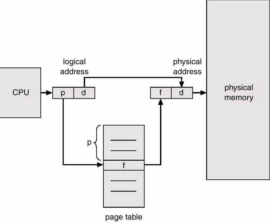
3. Logical address is divided into 2 parts
Page number (p) – Page table is indexed by page number.
Page offset (d) –
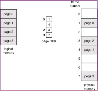
4. A page table is allocated to each process. (A pointer to page table is stored in PCB of process. )
Page table translates logical to physical addresses. Page 0 is in frame1, Page 1 is in frame 4 etc..
5. Internal fragmentation may occur due to paging.
Segmentation is a memory management scheme that support user’s view of memory.
When the user program is compiled, the compiler generates segments like
The code segment
Global variables segment
Heap memory segment
Stack segment etc..
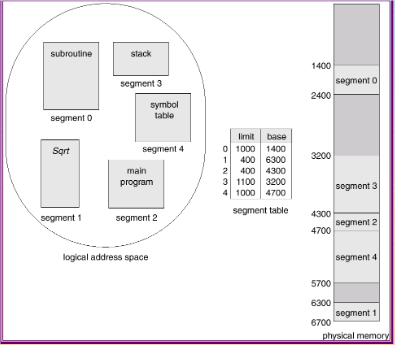
Each entry in segment table has
segment base (Starting physical address of segment) and
limit register (specifies the length of the segment).
Logical address is divided into 2 parts.
segment-number,
offset
Segment table is indexed by segment number.
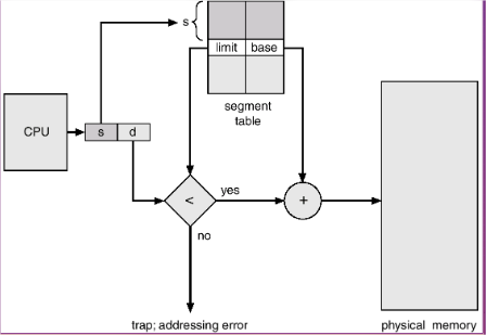
Segment-table base register (STBR) stores the location of segment table in main memory.
Segment-table length register (STLR) stores number of segments used by a program.
The segment number (say ‘s’) is used to find the entry in segment table. The required entry is ‘s’ locations away from the beginning of the segment table. Once the required entry in the segment table is found, the offset (‘d’) is compared with limit.
If( offset < limit) then offset is added with the base entry to generate the physical address.
Q) Explain the process concept?
A process is program in execution.
A process is an active entity and resides in main memory.
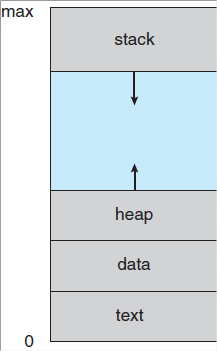
In main memory, process is allocated some space. This memory space is divided into 4 sections as shown
program code which is sometimes known as text section
Process stack: contains temporary data (Such as function parameters, return addresses and local variables)
Heap: is the memory allocated dynamically during process run time
Data section: contains global variables.
Although two processes are associated with the same program, they are considered as two separate execution sequences as the data, heap and stack sections differ even though text sections are equivalent
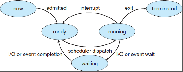
As a process executes, it changes state. Each process can be in one of the following states
New: the process is being created.
Running: Instructions are being executed
Waiting: a process is waiting for some event to occur (such as I/O completion etc..)
Ready: process is waiting to be assigned to processor
Terminated: the process has finished execution
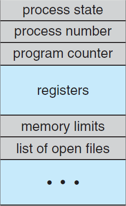
Each process is represented in the operating system by a process control block (PCB) or task control block. It contains information about
Process state: the state may be new, ready, running, blocked or terminated.
Program Counter : this register stores the address of next instruction to be executed.
CPU registers: like accumulators, stack pointers, index register and general purpose registers. The values of these registers are saved if the process is interrupted.
CPU scheduling information : like process priority, scheduling parameters etc.
Memory management information : include the values of base and limit register, segment tables, page tables etc
Accounting Information: include amount of CPU used, time limits, job or process number etc.
I/O status information : like list of I/O devices allocated to the process, list of open files, and so on.
Process System Calls:
int CreateProcess( char *progName, int argc, char *argv[ ])
progName is the program to run in the process
returns a process identifier (pid)
void Exit(int returnCode)
exits the process that executes the exit system calls
int Wait(int pid)
waits for a child process to exit
Q) Explain implementation of a simple operating system
answer:
Step-1 : There are three most important aspects to master prior to Operating System development. They are basics of computer science , basic programming and learning both high-level and low-level programming languages . Assembly languages or low-level languages are used to communicate directly with CPU ( Central Processing Unit ) . Each type of CPU speaks a machine language and there is just one corresponding assembly language for each type of CPU. x86 is the most used computer architecture and C is the most commonly used high-level programming language for the development of an Operating System .
Step-2 : The very next step in the development of an Operating System is to complete OS development tutorials.
https://www.youtube.com/watch?v=By6lWjiPpVI&list=PLG9aCp4uE-s17rFjWM8KchGlffXgOzzVP